 Xtremehardware
La nuova risorsa italiana di hardware e overclock
Specifications
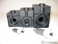
As we can see from the images to follow, each pump has 2 holes: one for incoming and one for the exit of the liquid. The center hole is the inlet while the other is the outlet, as indicated with the arrows on them. Both two are ¼ "G threaded holes.
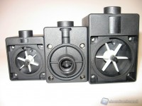
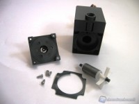
Unscrewing the 4 screws you can remove the cover, exposing the impeller.
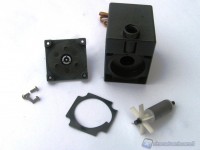
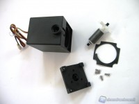
We note that the central pump, DC12-260, still has the lid mounted despite the 4 screws are removed, unlike the other 2 pumps, ie the smallest (DC12-220) and the most powerful of the series (DC12-400). Below is a photo of the detail where you can note the presence, in each pump, of an O-ring that acts as a seal.
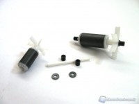
The impeller, held together by a magnetic cylinder, consists of 6 blades. As we see, it is completely removable for periodic cleaning.
The direction of rotation is counterclockwise, so that the pump pushes the water out. As central axis we find a ceramic pin, with 2 rubber supports at the ends that engage between the lid and the pump body.
